
TECHNICAL GUIDE / MECHANICAL SEAL SUPPORT SYSTEMS
Seal support vessel welding includes circular joints between the cylindrical vessel shell and its end caps, plus pipe nozzles, fittings and instrument connections on mechanical seal support assemblies. For suitable joints, automatic TIG welding can help maintain repeatability when the fixture, torch access, fit-up and qualified welding procedure are matched to the workpiece. This guide covers practical welding configurations, joint inspection and TIG equipment selection for vessel bodies and connections.
APPLICATION OVERVIEW
What this guide covers
- Where rotating-workpiece TIG welding is practical for vessel shells and end caps
- When fixed piping, nozzles, attachments or straight seams call for different equipment
- What to check before selecting a machine: fixture, clearance, qualified procedure and inspection
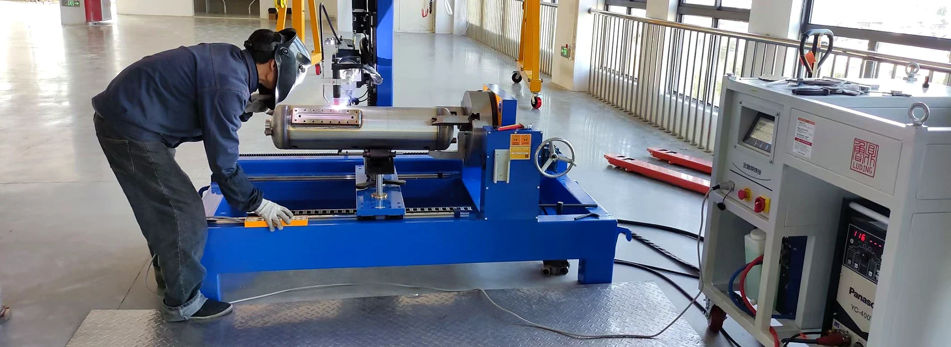
Automatic TIG welding station with a cylindrical vessel secured in a production fixture.
IN THIS GUIDE
Seal Support Vessels and Their Welded Connections
A seal support reservoir is part of the fluid management system around a mechanical seal. Our Mechanical Seal Support System Welding overview explains the wider system. This guide concentrates on welding reservoir shells, end caps, piping connections and attachments—and selecting fixtures and equipment for those joints.
Reservoir assemblies may include the vessel, tubing, valves and monitoring connections. For example, API Plan 52 uses an unpressurized buffer-fluid reservoir, while API Plan 53A uses a pressurized barrier-fluid reservoir. The specified piping plan and project requirements define what must be fabricated and verified.
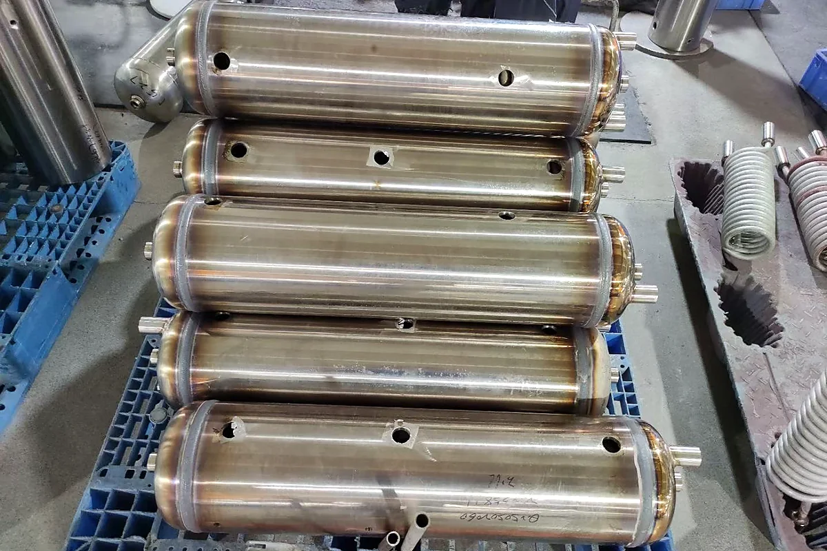
Finished stainless steel seal support reservoirs with welded end caps.
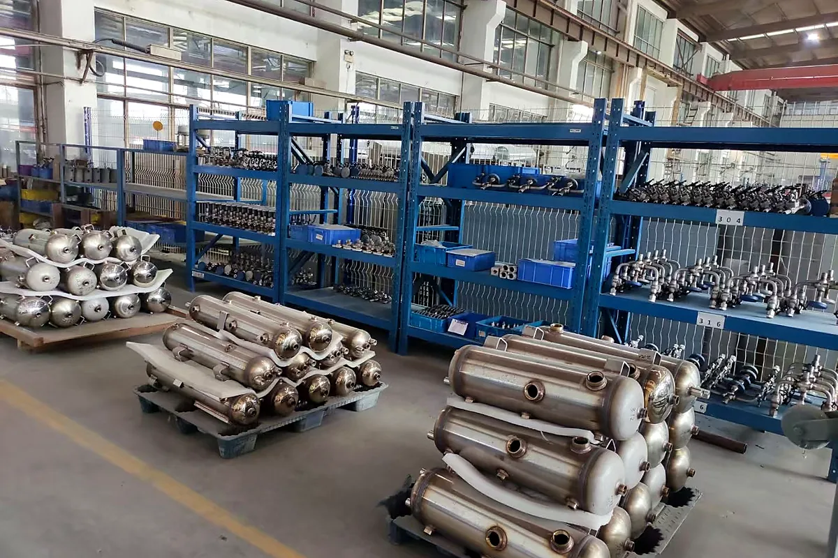
Cylindrical vessel components prepared for fabrication.
Seal Support Vessel Welding: Fit-Up and Quality Challenges
Seal pots and connected piping may contain circumferential shell-to-head welds, pipe-to-fitting joints and welded attachments close to instrument openings. Even when vessel designs vary, similar joints may appear repeatedly. Manufacturers need to maintain weld quality while accommodating different lengths, connections and customer requirements.
In seal support vessel welding, accurate fit-up is critical. Gaps, mismatch, out-of-roundness and inconsistent tack welds can affect a programmed weld. For stainless steel, cleaning, external shielding and—when required—internal gas protection influence the finished surface and root condition. These preparations remain essential whether welding is manual or automatic.
Joint-preparation checks before programming the weld
- Confirm base metal, wall thickness, joint type, cleanliness and the approved welding procedure
- Check shell roundness, end-cap alignment, weld gap and tack-weld consistency
- Verify fixture support, center of gravity, unobstructed torch travel and cable clearance
- Determine whether internal purging or backing gas is necessary for the material and joint
- Document inspection and leak-testing requirements before running production samples
Automatic TIG Welding Methods for Vessels and Connections
1. Vessel shell and end-cap circumferential welds
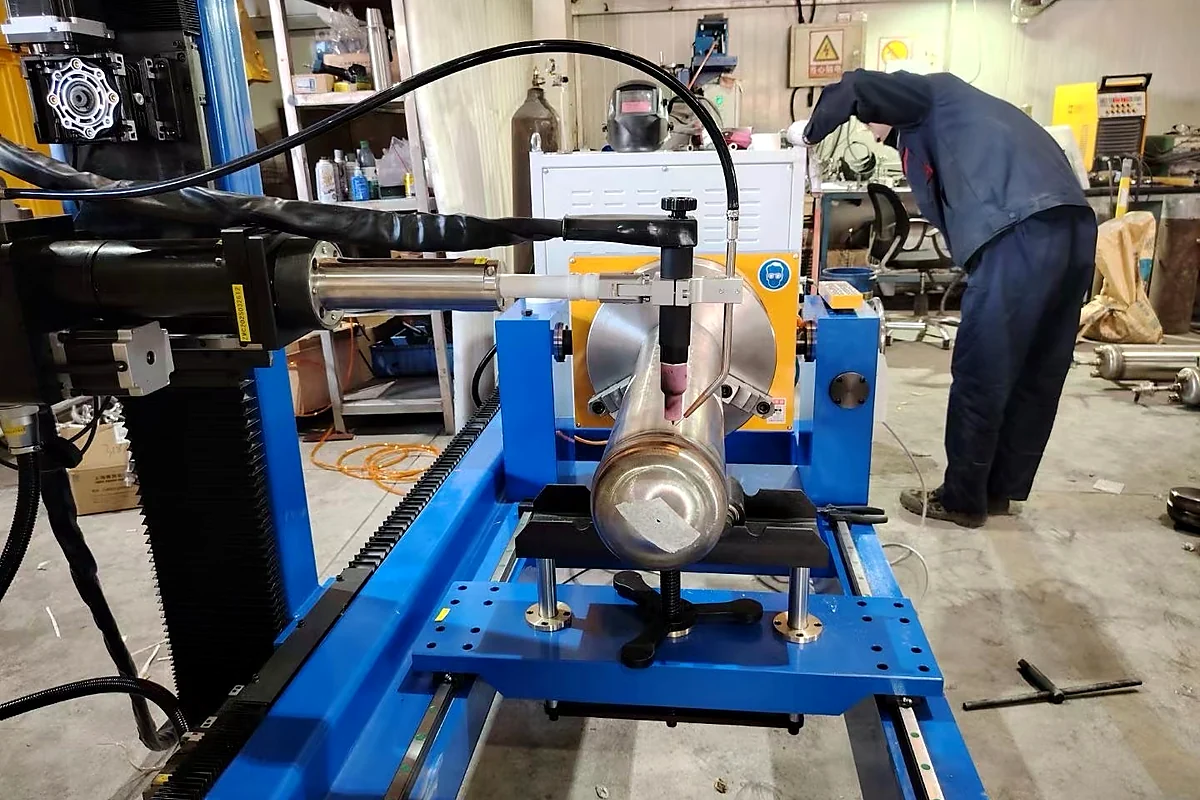
For seal support vessel welding on a cylindrical shell-to-end-cap joint, the workpiece may be held and rotated beneath a positioned TIG torch if the fixture safely supports it. Controlled rotation and stored welding parameters can help repeat an approved welding procedure across suitable circular joints.
Fixturing must secure the vessel without distorting the shell or damaging finished surfaces. Check the vessel diameter, length, weight, center of gravity, end-cap geometry and clearance for fittings and supports before selecting equipment.
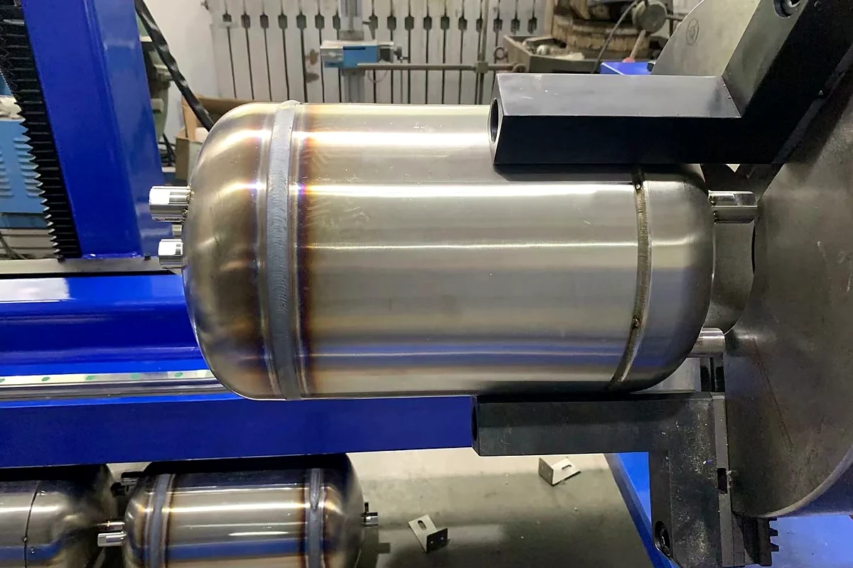
A cylindrical vessel mounted in a rotary welding fixture.
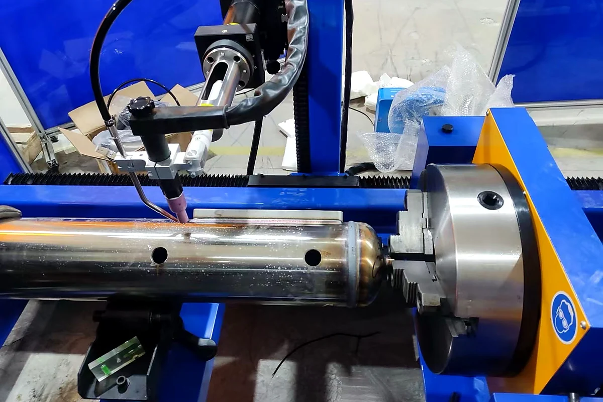
Torch and workpiece positioning for a circumferential weld.
2. Seal support piping and fittings
Seal support vessel welding projects may also include short pipe and tube runs between the vessel, instruments and mechanical seal. Depending on the design, fabricators may complete pipe-to-pipe, pipe-to-flange or pipe-to-fitting welds before final assembly. A rotating-workpiece welding center can be useful when the component can be securely clamped and the joint remains accessible.
Small-bore connections need careful attention to clamping, torch clearance and root-side protection. If the pipe is fixed within a tight assembly, an orbital or another dedicated configuration may be appropriate, provided access and joint geometry permit it. Related reading: how automated pipe-to-flange welding works.
3. Attachments and non-circular welds
Gauge connections, brackets and other welded attachments may follow straight, rectangular or irregular paths. A basic circular welding program cannot automatically follow every geometry. Depending on the part, these joints may require programmed multi-axis motion, special tooling, a separate station or manual welding. A drawing or physical sample is the best starting point for evaluating the process.
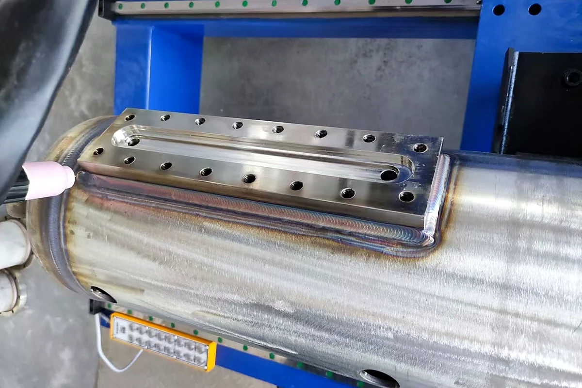
Close-up of a welded attachment on a cylindrical vessel.
4. Longitudinal seams where required
Where a vessel shell is formed from rolled plate, its longitudinal seam is a separate operation from the circumferential end-cap welds. A straight-seam welding configuration or dedicated seam welder may be considered according to shell length, material, thickness, joint preparation and the qualified welding procedure. Not every seal pot uses the same shell construction.
Choosing TIG Equipment for Vessel and Connection Welding
For suitable seal support vessel welding tasks, consider dedicated rotating-workpiece TIG welding centers for accessible circular shell-to-head joints. MECANEXT’s H1440-T and H3660-T are examples to evaluate, not automatically interchangeable solutions. Compare each model’s verified chuck clamping range and through-bore, workpiece length and weight, support arrangement, torch reach and required joint geometry. Final suitability must be checked against current machine specifications and the actual workpiece.
Depending on the model and configuration, relevant functions may include programmable rotation, current control, arc-length adjustment, torch oscillation and wire feeding. Match each required option to the joint design and approved procedure rather than choosing a machine by feature count alone.
Equipment Selection at a Glance
| Workpiece or joint | Configuration to assess | What to verify |
|---|---|---|
| Rotatable reservoir shell-to-head joint | Rotating-workpiece TIG welding center | Chuck fit and through-bore, vessel mass and length, support, center of gravity and torch access |
| Fixed or assembled small-bore piping | Orbital or other dedicated welding setup | Head clearance, root access, joint geometry and shielding requirements |
| Rolled-plate shell longitudinal seam | Straight-seam welding equipment | Shell length, longitudinal fit-up, thickness and qualified procedure |
| Instrument attachments and irregular weld paths | Dedicated tooling, programmed motion or manual welding | Actual weld path, clamping method, torch reach and accessibility |
Indicative selection guide. Confirm capacities and process suitability using workpiece details and current machine specifications.
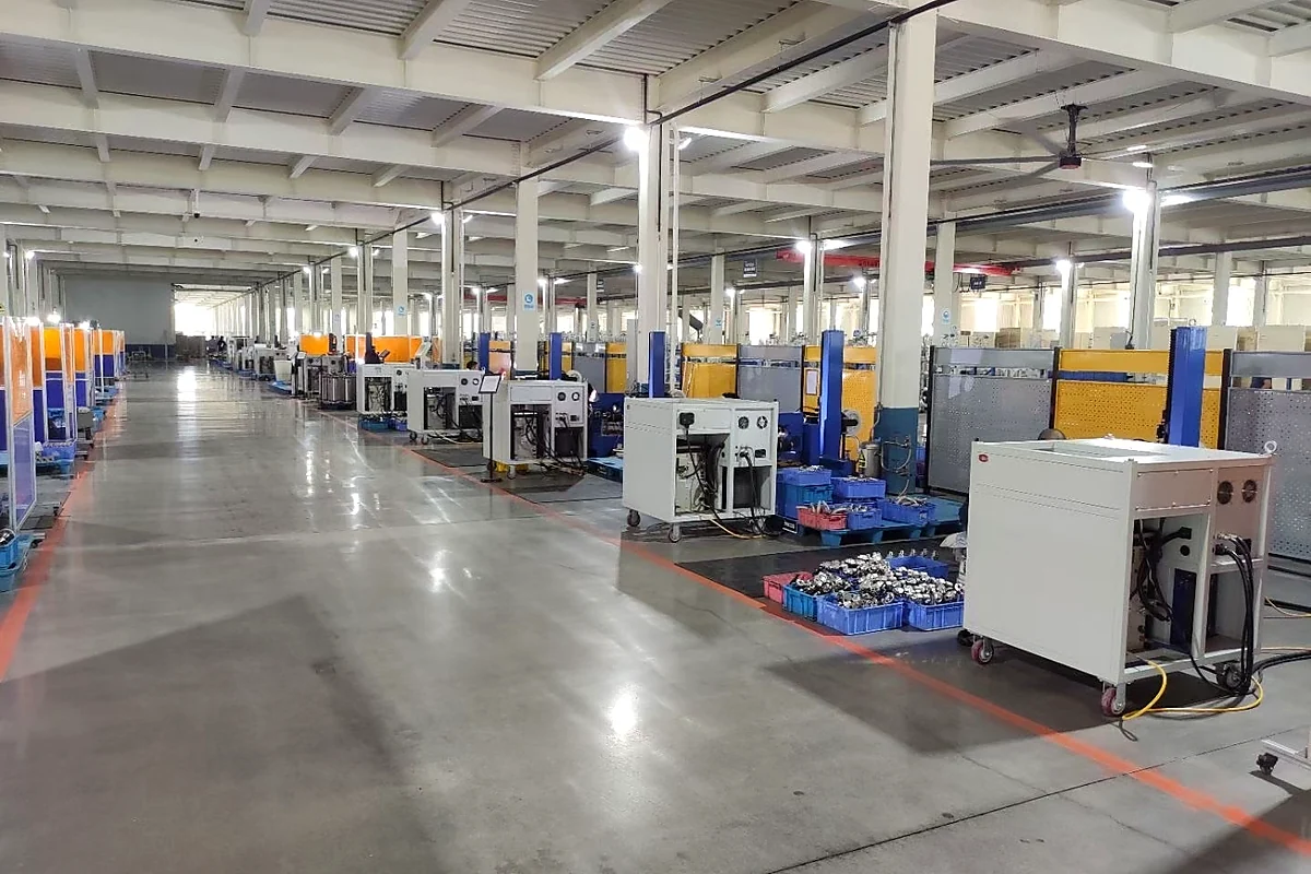
Real automatic TIG welding stations inside the manufacturing workshop.
For seal support vessel welding, distinguish chuck clamping range from center through-hole diameter: a vessel held by the jaws may not pass through the spindle. Also verify workpiece mass, length, center of gravity, supports, torch clearance and loading method, especially with protruding nozzles or fittings. Not sure which configuration fits? Request an application review with a workpiece photo or short description. Drawings and a complete machine specification are not required for an initial inquiry. See our automatic pipe welding machine selection guide for related criteria.
Joint Preparation, Inspection and Weld Verification
Before a production run, verify surface cleaning, fit-up, tack placement, alignment, shielding and any required internal gas protection. Turn these checks into repeatable setup instructions alongside the approved welding procedure.
For pressure-retaining components, follow the project’s applicable code and approved welding procedures, personnel qualifications, material controls and examination requirements. Inspection may include visual examination, liquid penetrant testing, radiography or other specified methods. Pressure and leak tests must follow the approved design and test procedure. A uniform-looking bead alone does not establish internal weld integrity or code compliance.
QUALITY CONTROL
A consistent bead is not the same as a verified weld. Follow the inspection, qualification and leak-testing requirements of the applicable design and procedure.
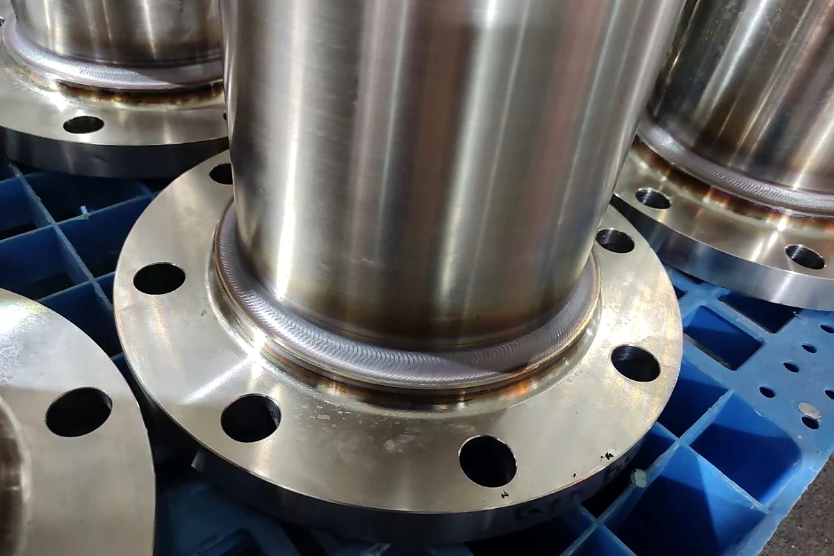
TIG weld detail on a stainless steel pipe-to-flange joint.
Sample-Weld Workflow Before Equipment Approval
A sample-welding trial should answer four practical questions: can the part be fixtured safely, can the weld be completed repeatably, does it meet the specified inspection criteria, and does the full production cycle justify the equipment?
01 / PROCESS CHECK
Drawing and workpiece review
Confirm dimensions, material grade, wall thickness, joint geometry and production mix. Use representative samples for unfamiliar fit-up or restricted torch access. The trial should represent the actual component, not only an idealized test coupon.
02 / PROCESS CHECK
Fixture and rotation verification
Set the vessel in the fixture and confirm alignment, loading clearance and stable rotation before welding. On thin-wall shells, check that clamping loads do not introduce ovality or distort the weld joint.
03 / PROCESS CHECK
Welding procedure trial
Use a qualified or appropriately developed procedure for the relevant joint. Check welding current, travel speed, shielding, filler-wire requirements and root-side protection where applicable. Avoid copying parameters from a different geometry without verification.
04 / PROCESS CHECK
Inspection and production evaluation
Inspect the sample against the project requirements before accepting production settings. Compare the entire cycle—including preparation, fixturing, welding, inspection, changeover and rework—with the current process to assess practical automation benefits.
How to Evaluate Productivity and Return on Investment
When assessing productivity for seal support vessel welding, compare actual preparation, loading, welding, changeover, inspection and rework time for a representative batch before and after an automatic-welding trial. Arc-on time alone does not establish a production benefit.
Annual volume and the range of joint types are important. A machine used frequently for repeatable work may deliver more value than one used occasionally on unique assemblies. Include fixtures, training, consumables, maintenance and floor space in the investment calculation. An indicative simple payback period is initial investment divided by estimated annual net savings, provided net savings are positive. Validate any estimate using actual production data.
Frequently Asked Questions
Not every joint suits the same automatic welding setup. Accessible circular shell-to-head seams and repeatable pipe connections may suit rotating-workpiece TIG equipment. Instrument attachments, restricted-access joints and non-circular paths may require dedicated tooling, another programmed process or manual welding. Review the workpiece and weld path before choosing equipment.
No. TIG/GTAW is often selected for controlled welds on stainless steel and precision connections, but other processes may be appropriate depending on material, thickness, joint design and production requirements. The selected process must meet the applicable welding procedure and acceptance criteria.
No. Automation does not by itself demonstrate compliance with an API piping plan or an applicable design and fabrication code. System design, materials, approved welding procedures, required qualifications, inspections and leak or pressure tests must satisfy the project’s specified requirements. Verify the governing standards and the particular piping plan.
For an initial review, share the workpiece or joint type, material, approximate diameter and length, wall thickness, weight, weld locations, access restrictions and expected volume where known. A photo or short description is enough to start; drawings, samples and inspection requirements are helpful for detailed equipment selection but not mandatory for an initial inquiry.
Internal shielding or backing gas may be needed depending on the metal, weld root configuration, corrosion or cleanliness requirements and approved welding procedure. It should be evaluated for the actual material and joint rather than assumed for every component.
No. The chuck clamping range and center through-hole are different dimensions. Also check the part’s weight, length, center of gravity, rotational clearance, fixture access and the required welding process.
MECANEXT / APPLICATION REVIEW
Discuss Your Vessel and Connection Welding Application
Working on a seal support vessel welding application? Tell us whether the main joint is a vessel body seam, an end-cap weld, a pipe nozzle or a fitting. A brief message or workpiece photo is enough to start; drawings and final equipment specifications are optional. MECANEXT can help evaluate a suitable automatic TIG welding setup.
Or email sales@mecanext.com with a short description or photo. No drawings required to start.