
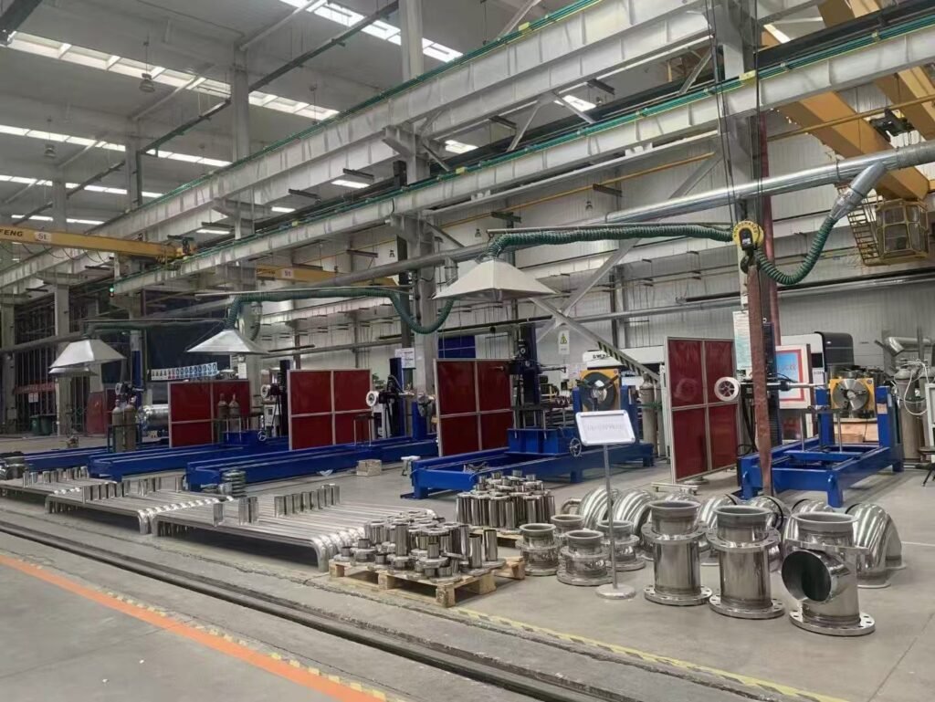
Data Center Liquid Cooling Pipe Welding is becoming increasingly important as AI servers and high-density computing drive higher cooling demands. From facility-level rigid piping to CDU piping and liquid cooling manifolds, stainless steel cooling circuits require reliable weld quality, leak tightness, and consistent production.
For liquid cooling piping manufacturers, cooling performance is not the only concern. Another fundamental challenge is how to achieve stable and repeatable welding across a large number of pipes, fittings, and connections.
From external rigid piping and manifolds to CDU piping, different structures require different welding processes—and therefore different automated welding solutions.
1. Rigid Cooling Pipes: Automatic TIG Welding for Consistent Circumferential Welds
External liquid cooling pipelines in data centers typically include numerous straight pipes, elbows, flanges, and other fittings. This creates a large number of pipe-to-pipe and pipe-to-flange circumferential welds.
Depending on pipe diameter, wall thickness, and joint design, several automatic TIG welding processes can be applied:
- Rotary automatic TIG welding
- Open-head orbital TIG welding
- Cold-wire or hot-wire TIG welding
- Multi-layer, multi-pass automatic welding
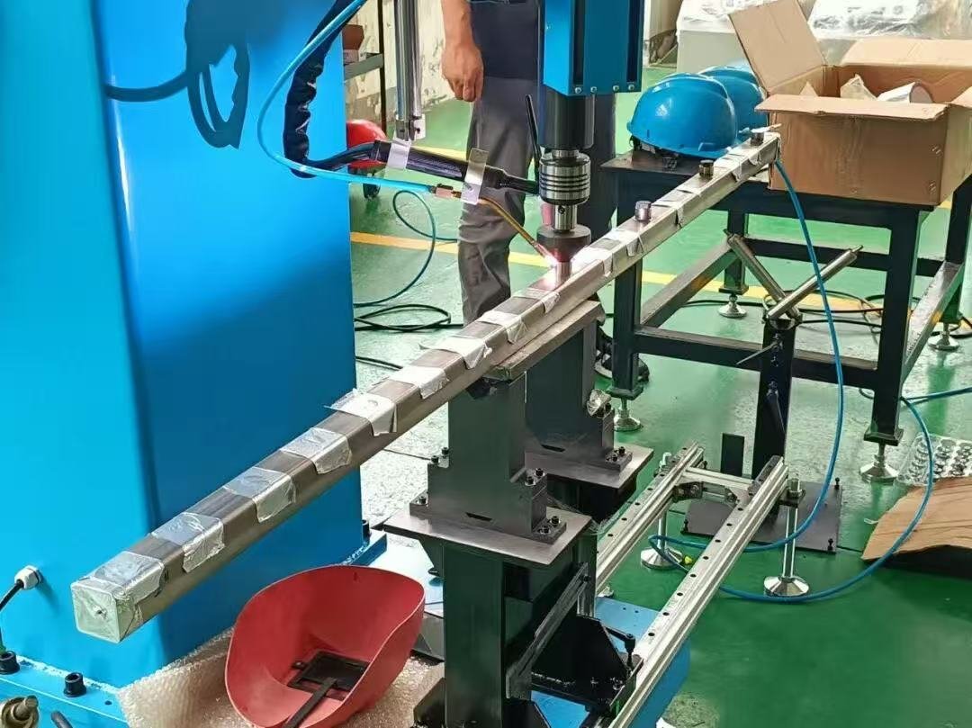
For thicker pipes, the welding system can automatically perform root, fill, and cap passes according to preset programs. Welding current, wire feed speed, rotation speed, torch oscillation, and arc length can all be controlled automatically.
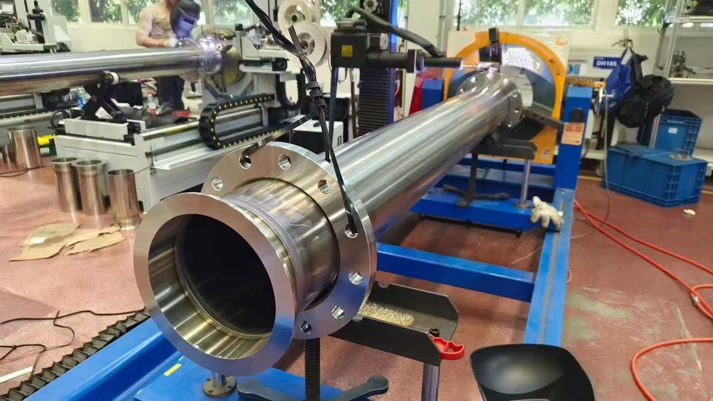
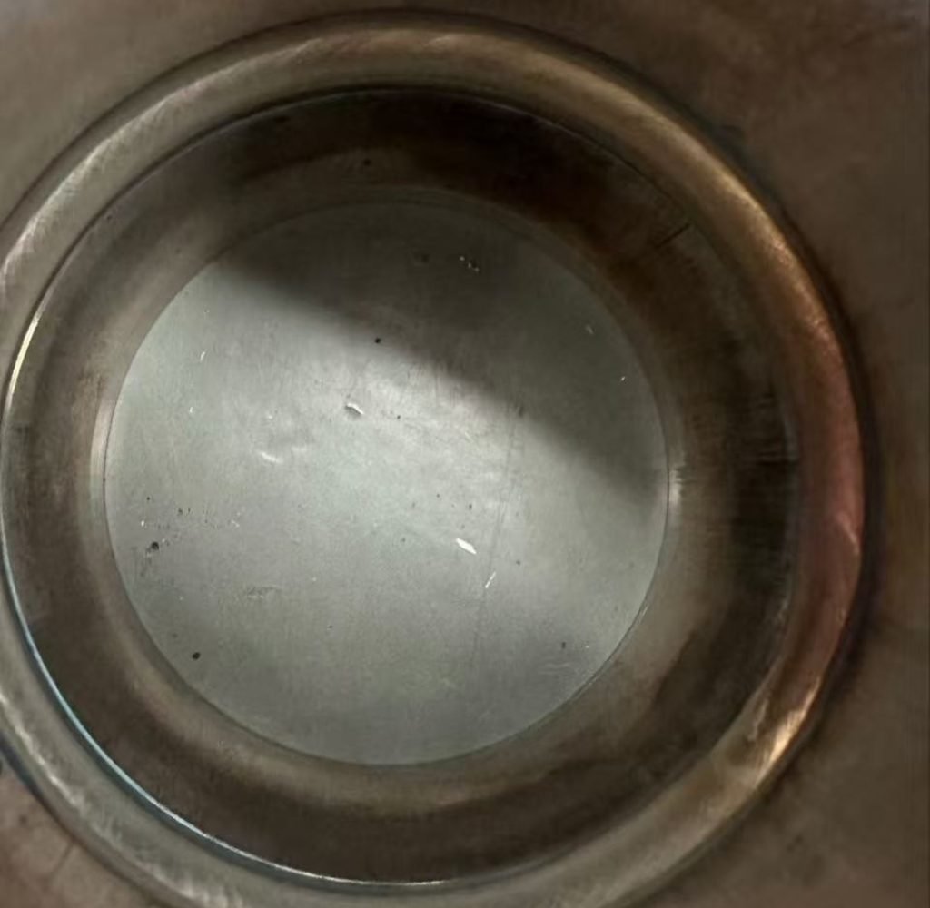
Compared with manual welding, the main value of automation is not simply higher welding speed. More importantly, it helps maintain consistent penetration, heat input, and weld appearance across dozens or even hundreds of circumferential welds.
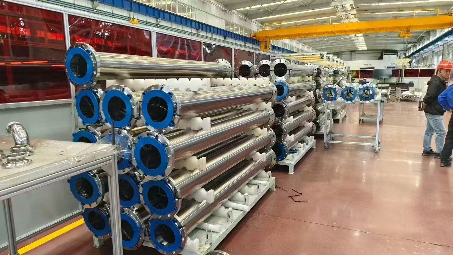
2. Liquid Cooling Manifolds: Controlling Multi-Branch Welding and Thermal Distortion
A liquid cooling manifold typically contains multiple branch pipes, fittings, or connection ports welded onto a main pipe.

The primary challenge is not a single weld, but the combination of multiple closely spaced joints and concentrated welding heat.
Continuous manual welding may result in main-pipe distortion, branch angle deviation, interface displacement, and inconsistent weld quality.
For this application, dedicated positioning fixtures can be combined with automatic TIG or laser welding systems.
The fixture maintains the position of the main pipe and branches, while programmed control of the welding path, speed, and heat input reduces variations caused by manual operation.
Regular circular joints can use automatic circumferential TIG welding. For more complex branch connections, customized rotary mechanisms, torch motion systems, or dedicated welding fixtures can be designed according to the manifold structure.
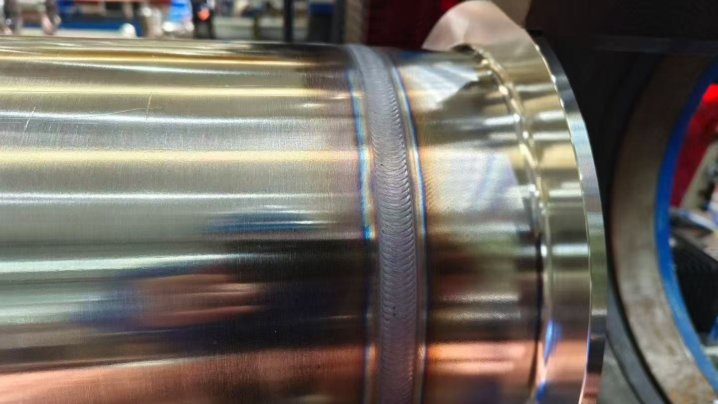
For high-volume manifold production, the key question is no longer simply whether the joint can be welded, but how every connection can be welded repeatedly using the same process parameters.
3. CDU Piping: Precise Heat Input for Small-Diameter, Thin-Wall Tubes
Piping inside and around the Coolant Distribution Unit (CDU) typically has smaller diameters, thinner walls, more compact layouts, and densely arranged connections.
For these components, manual TIG welding can be affected by operator technique, assembly gaps, and variations in heat input.
Depending on tube diameter and structure, suitable processes include:
- Small-diameter automatic TIG welding
- Rotating-torch automatic welding
- Laser welding for thin-wall stainless steel tubing
For small-diameter, thin-wall stainless steel pipes in particular, laser welding offers high welding speed, a small heat-affected zone, and low distortion, making it suitable for batch production of CDU piping components.
For complex piping assemblies that cannot rotate, the workpiece can remain stationary while the welding torch rotates around the joint to complete automatic circumferential welding.
Choosing the Right Automatic Welding Process for Liquid Cooling Piping
There is no single welding machine that can handle every joint in a data center liquid cooling piping system.
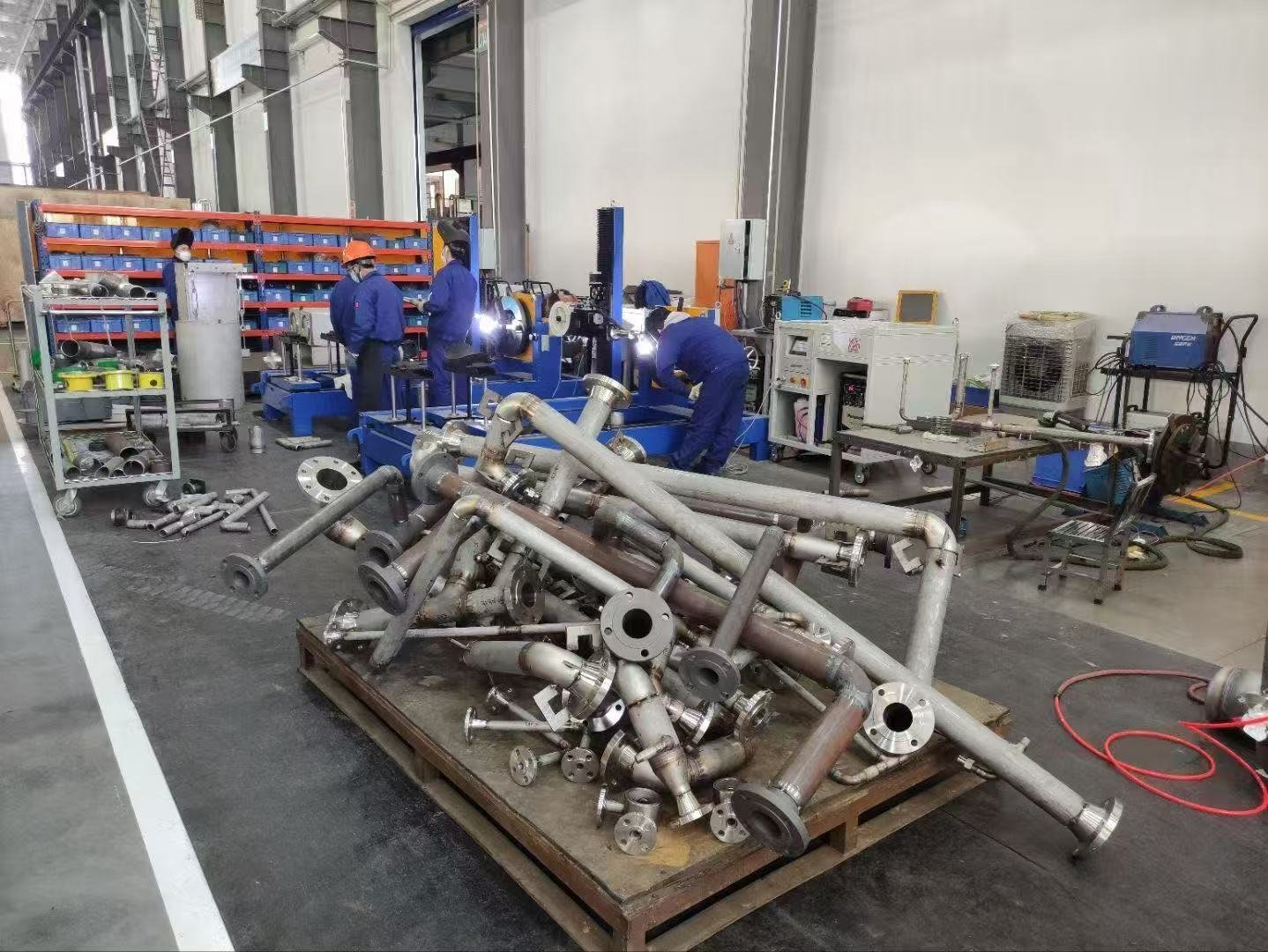
The key is to match the welding process to the specific product structure:
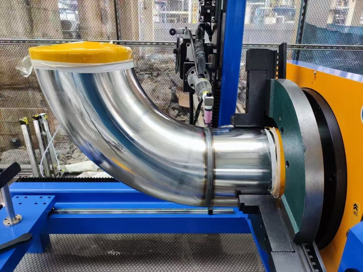
External rigid pipes → Automatic TIG / Orbital TIG / Multi-pass welding
Liquid cooling manifolds → Dedicated fixtures + Automatic circumferential or branch welding
CDU small-diameter piping → Small-diameter automatic TIG / Laser welding
Depending on the application, the welding system can also integrate automatic wire feeding, torch oscillation, AVC arc length control, multi-layer and multi-pass programs, internal argon purging, dedicated positioning fixtures, and welding parameter storage.
As data center liquid cooling piping moves from small-batch manufacturing toward large-scale production, welding automation becomes increasingly valuable.
From external rigid pipes and liquid cooling manifolds to CDU piping, the goal is the same: to make every welded connection more consistent, repeatable, and suitable for scalable manufacturing.
Frequently Asked Questions (FAQ)
1. What welding process is suitable for data center liquid cooling pipes?
Automatic TIG welding is widely suitable for stainless steel liquid cooling pipes because it provides stable heat input, consistent penetration, and repeatable weld quality. Orbital or rotary TIG welding can be selected according to pipe diameter and joint structure.
2. Can automatic TIG welding be used for liquid cooling manifolds?
Yes. Automatic TIG welding can be applied to circumferential joints and multiple branch connections on liquid cooling manifolds. Customized fixtures and welding motion systems can also be used for complex manifold structures.
3. How do you choose a welding solution for liquid cooling piping?
The welding solution should be selected according to pipe diameter, wall thickness, joint type, production volume, and product structure. Rigid pipes, manifolds, and CDU piping may require different automatic welding configurations.