
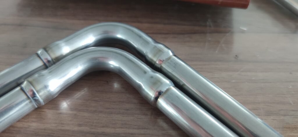
High-pressure hydraulic tubes, bent tubes and complex tube assemblies are widely used in construction machinery, hydraulic systems, automotive manufacturing, energy equipment, industrial machinery and many other applications. Choosing the right hydraulic tube welding machine is essential for achieving consistent weld quality across straight tubes, bent tubes, fittings and complex tube assemblies.
Typical components may include straight tubes, 90-degree bends, multi-bend tubes, hydraulic fittings, flanges, branch connections and other irregular tube assemblies.
For repetitive production, automatic TIG welding can significantly improve weld consistency and reduce dependence on manual welding skills.
However, there is one important point:
Different tube geometries require different automatic welding methods.
A welding system that works perfectly for a short straight tube may not be suitable for a complex three-dimensional bent tube assembly.
In general, automatic welding solutions for hydraulic tubes and tube assemblies can be divided into several configurations.
1. Straight and Short Tubes: Rotate the Workpiece and Keep the Torch Stationary
For short tubes, straight tubes and relatively simple tube assemblies, the most common configuration is:
Workpiece rotation + stationary TIG torch
The tube is clamped by a chuck or dedicated fixture and rotates around its own centerline, while the welding torch remains stationary.
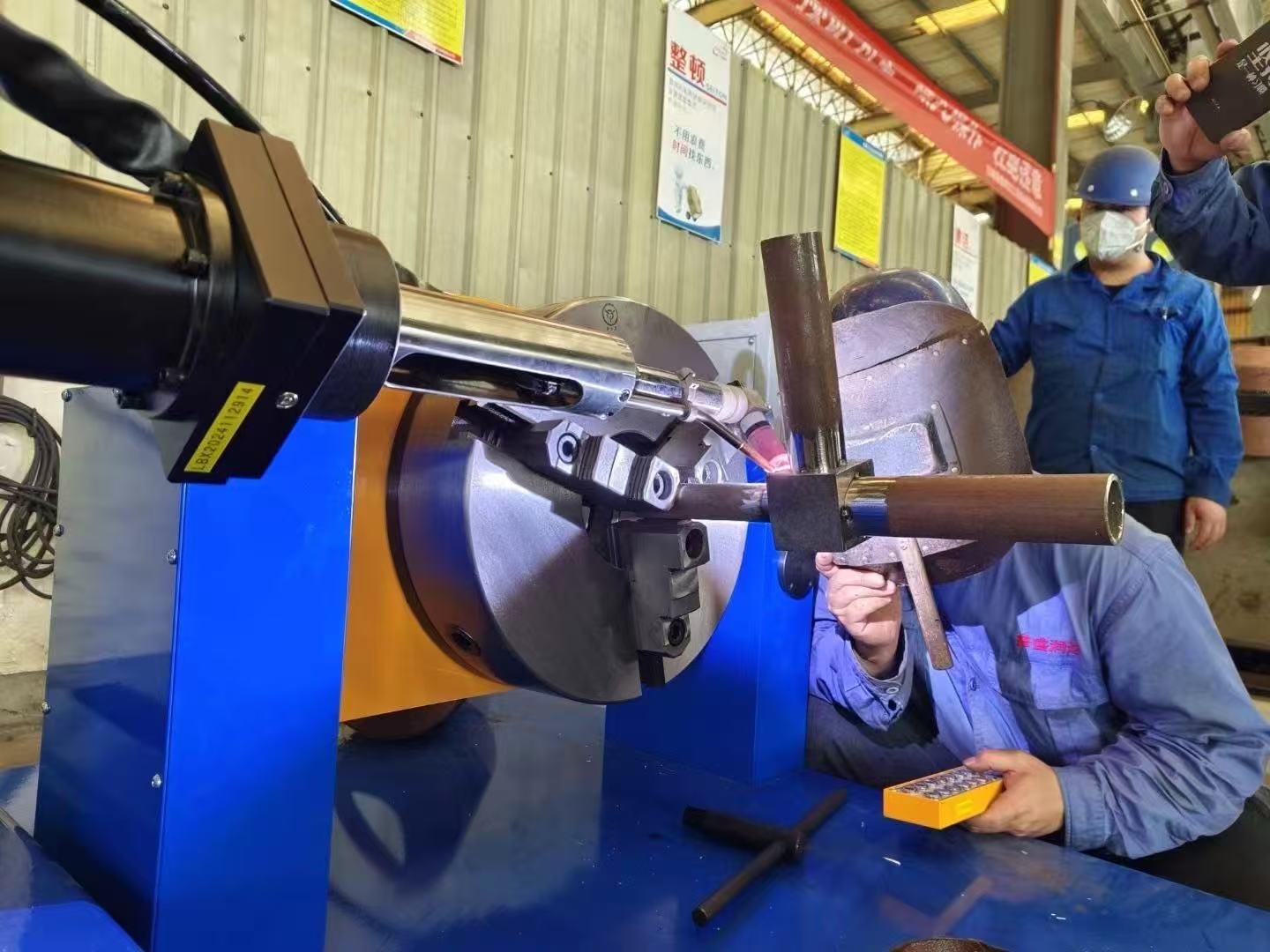
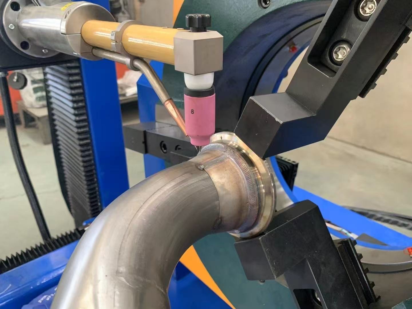
This type of automatic tube welding machine can be used for various circumferential welds, including:
- Tube-to-tube butt welding
- Tube-to-fitting welding
- Tube-to-flange welding
- Circumferential fillet welding
- Autogenous TIG welding
- TIG welding with filler wire
Why is this welding method so stable?
The main advantage is that the welding torch remains almost in the same position throughout the entire welding cycle.
The relationship between the tungsten electrode, filler wire and weld pool remains relatively constant.
The torch angle, wire feeding position, arc length and effect of gravity on the weld pool are also easier to control.
For this reason, if the workpiece can rotate freely through 360 degrees, rotating the workpiece while keeping the welding torch stationary is normally one of the most stable methods for automatic circumferential welding.
This configuration is especially suitable for batch production of relatively straight and compact tube components.
However, the situation changes when the product becomes a bent or irregular tube assembly.
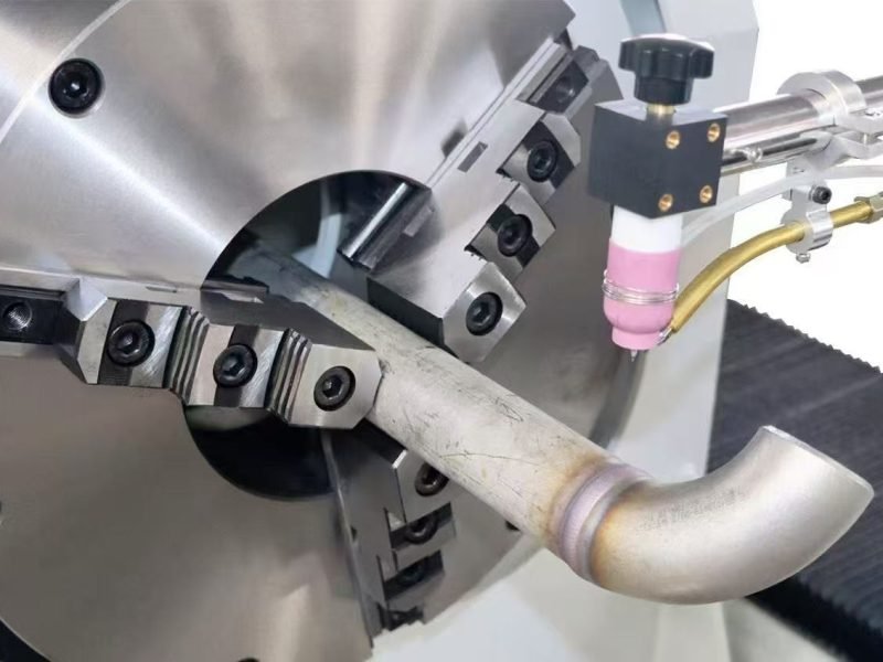
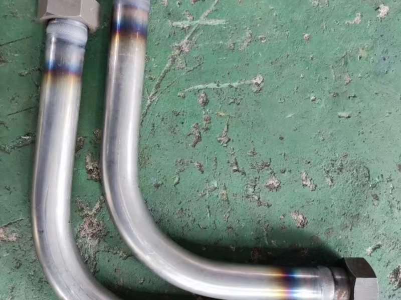
2. Why Are Bent Tube Assemblies More Difficult to Weld Automatically?
Hydraulic tube assemblies frequently contain bends and fittings, such as:
- 90-degree bent tubes
- U-shaped tubes
- S-shaped tubes
- Multi-bend tubes
- Three-dimensional bent tubes
- Tubes with hydraulic fittings
Tube-to-flange assemblies
- Complex tube assemblies with several welded components
If a conventional workpiece-rotation machine is used, the entire bent tube must rotate around the weld centerline.
For a simple straight tube, this is not a problem.
For a complex bent tube, however, the rotating envelope can become extremely large.
The tube may interfere with the:
- Machine frame
- Welding torch
- Wire feeder
- Fixture
- Other sections of the workpiece
Long tubes and three-dimensional bent tube assemblies may not be able to rotate through 360 degrees at all.
Therefore, for bent tube welding, the better solution is often to reverse the motion:
Keep the tube stationary and rotate the welding torch around the joint.
Depending on the wall thickness and joint configuration, several different welding systems can be used.
3. Thin-Wall Bent Tubes: Closed Orbital TIG Welding
For thin-wall tubing, one of the most effective solutions is an orbital TIG welding machine.
The workpiece remains stationary while the tungsten electrode rotates 360 degrees around the tube.
This means the entire bent tube does not need to rotate.
As long as there is sufficient space around the weld joint for the orbital welding head, the process can be used on many bent tube assemblies.
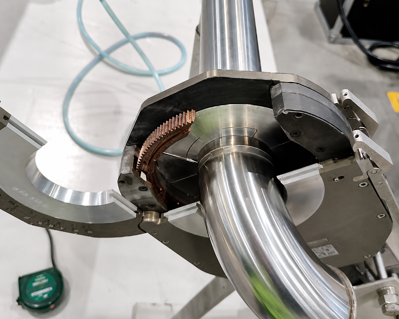
For thin-wall tubes with accurate fit-up, autogenous TIG welding can normally be used.
Autogenous welding means that no filler wire is added.
The two tube ends are melted and fused together by precisely controlling parameters such as:
- Welding current
- Pulse current
- Rotation speed
- Welding sectors
- Shielding gas
- Internal purge gas
This type of orbital tube welding is particularly suitable for precision thin-wall applications where repeatability and weld appearance are important.
Typical applications include:
- Thin-wall stainless steel tubes
- Hydraulic tubing
- Instrumentation tubing
- Liquid cooling tubes
- Automotive fluid lines
- Aerospace tubing
- Other precision tube assemblies
The main advantage is simple:
The tube remains stationary while the tungsten electrode automatically travels around the complete circumference.
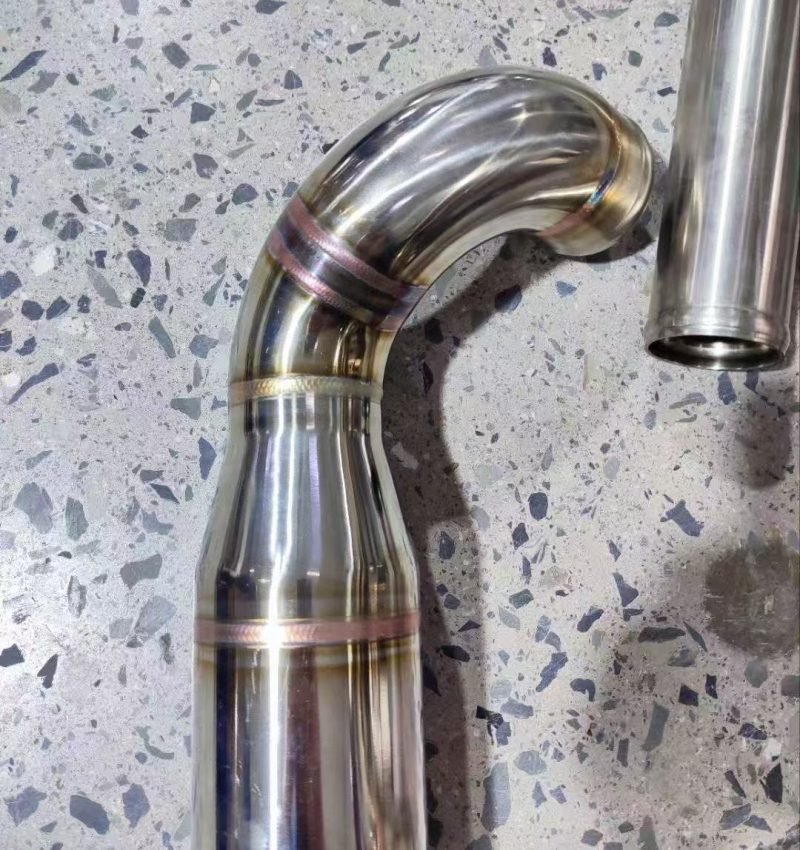
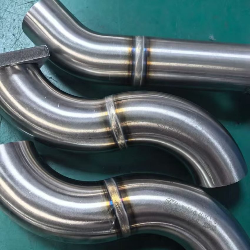
4. Thick-Wall Tubes: Open Orbital TIG Welding with Filler Wire
When the tube wall becomes thicker, autogenous TIG welding is often no longer sufficient.
Depending on the wall thickness, groove design and welding procedure, filler metal may be required.
For these applications, an open orbital TIG welding head with automatic filler wire feeding can be used.
The welding head is clamped around the tube while the TIG torch rotates around the joint.
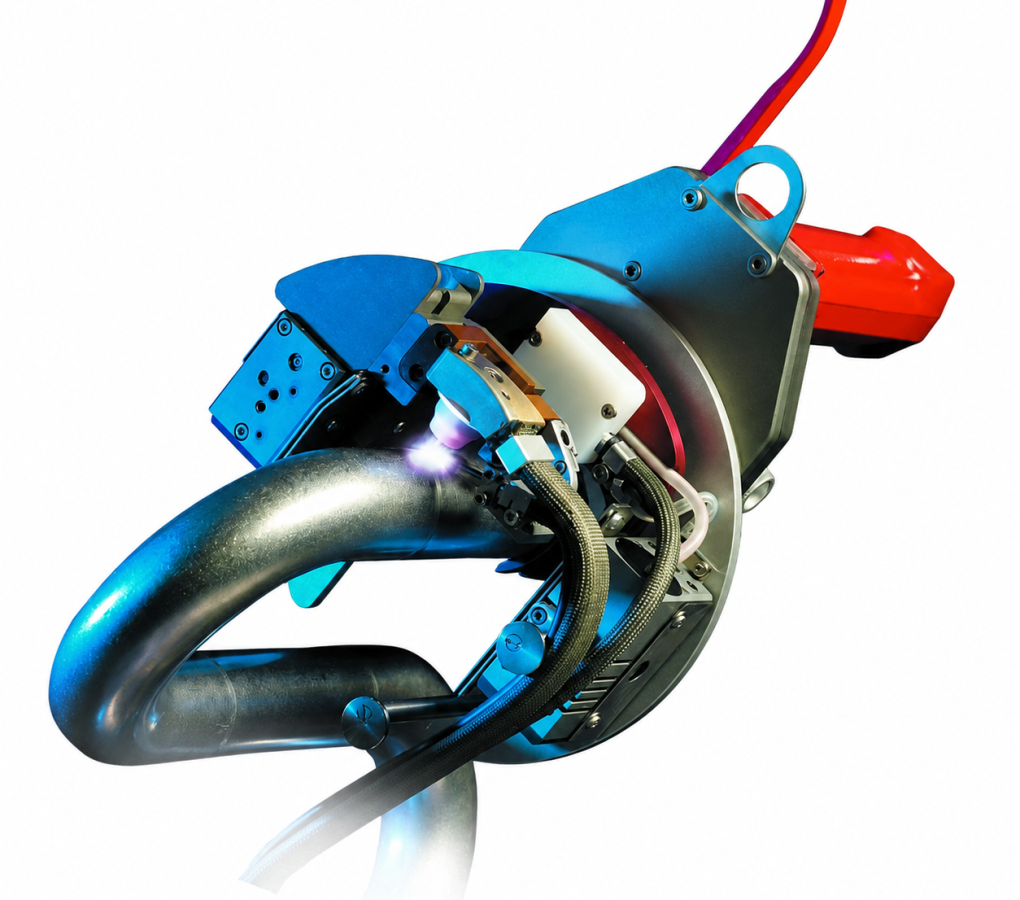
Unlike a closed orbital welding head for thin-wall fusion welding, an open orbital welding system provides more space for:
- Automatic filler-wire feeding
- Arc Voltage Control (AVC)
- Torch oscillation
- Multi-pass welding
- Multi-layer welding
This makes it more suitable for medium- and thick-wall tube-to-tube butt welding.
For thicker joints, the welding process may include:
Root pass → Fill passes → Cap pass
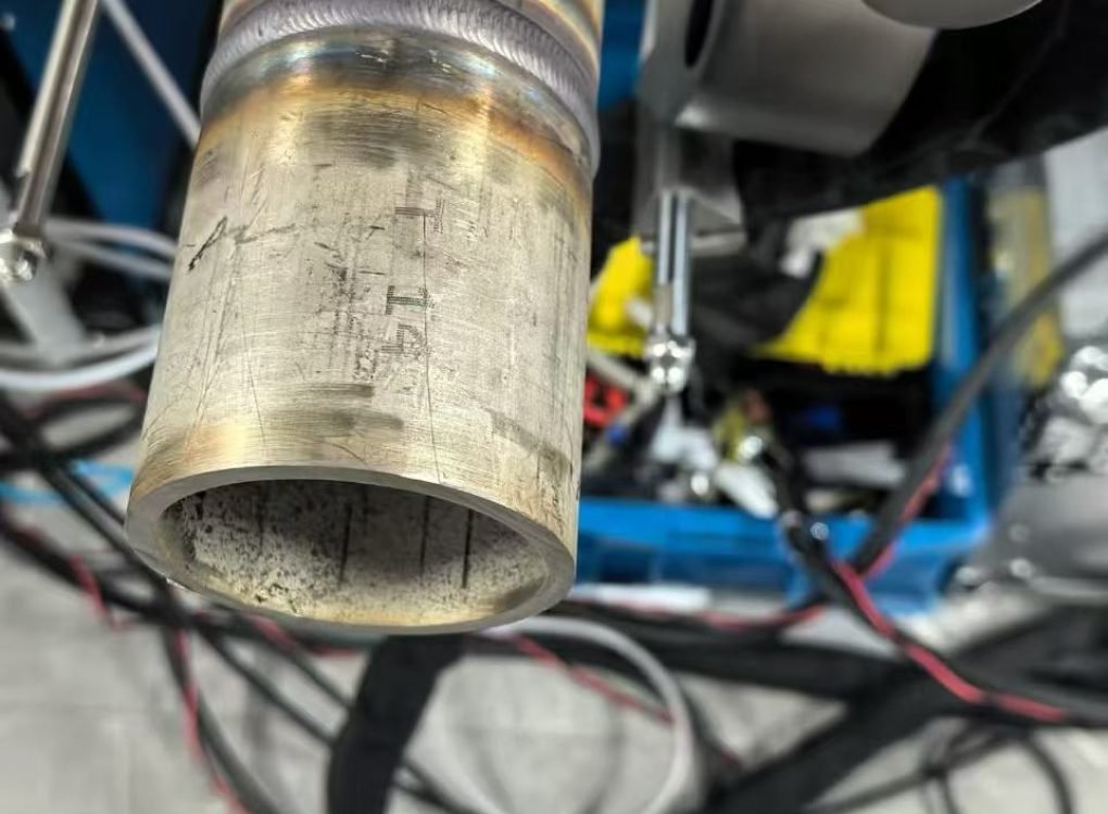
Different welding parameters can also be programmed for different layers and different circumferential welding positions.
AVC can be used to maintain the required distance between the tungsten electrode and the workpiece, while torch oscillation can be added when the weld groove becomes wider.
Therefore, for thicker tube-to-tube joints, a clamp-on open orbital TIG welding machine with filler wire provides significantly greater process capability than a standard closed orbital welding head.
However, orbital welding still has one important limitation:
The welding head must physically fit around the weld joint.
This becomes particularly important for complicated tube assemblies.
5. Why Is Orbital Welding Difficult for Fittings on Complex Bent Tubes?
Consider a complex hydraulic tube assembly with:
- Multiple bends
- Short straight sections
- Hydraulic fittings
- Flanges
- Elbows close to the weld joint
Even though an orbital welding head does not require the tube itself to rotate, the welding head still needs enough space to clamp around the tube and rotate around the joint.
If a fitting is located very close to a bend, the orbital head may interfere with the bent section.
If the straight section is too short, the head may not have enough space for installation.
When the assembly contains several closely positioned fittings, this problem becomes even more obvious.
Therefore:
Orbital welding is an excellent solution for tube-to-tube butt welds, but it is not always the best solution for welding fittings onto complex bent tube assemblies.
For these applications, a dedicated rotary torch automatic TIG welding machine is often more suitable.
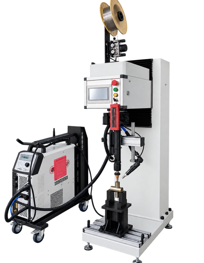
6. Rotary Torch TIG Welding for Complex Bent Tube Fittings
For hydraulic fittings, flanges and other components welded onto irregular bent tubes, a highly effective solution is:
Stationary workpiece + rotating welding torch
The bent tube assembly is fixed vertically in a dedicated fixture.
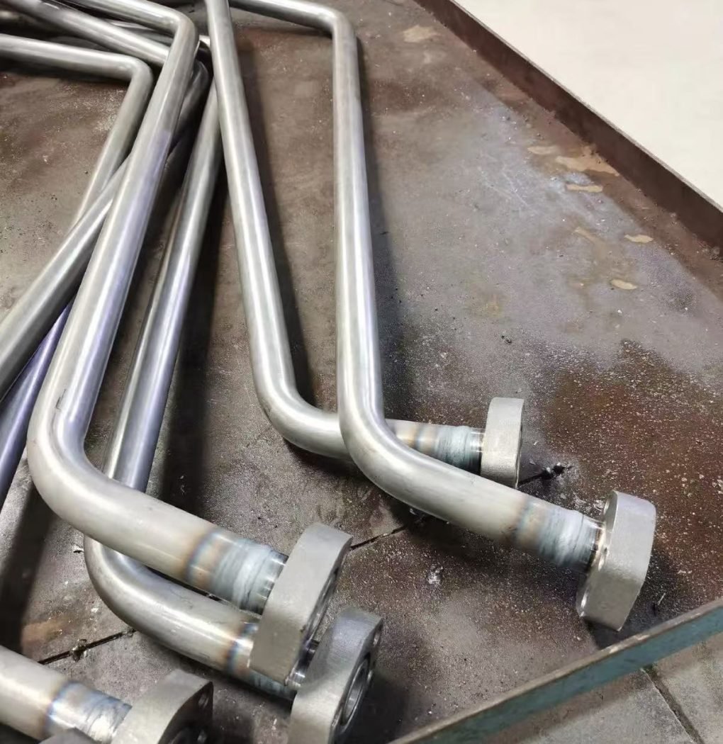
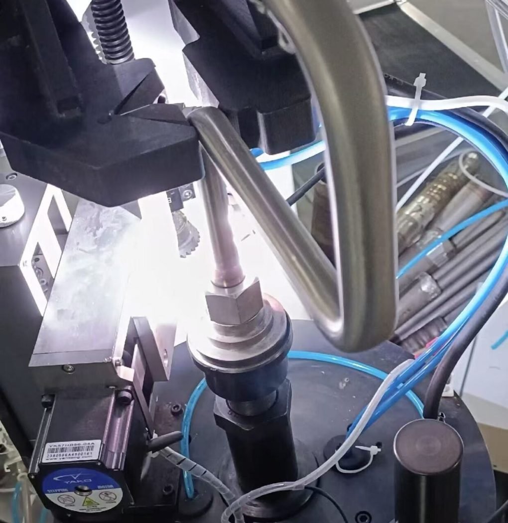
Instead of rotating the complete tube assembly, the TIG torch rotates 360 degrees around the fitting or tube joint.
This type of rotary torch welding machine is particularly suitable for complex tube assemblies that cannot be rotated.
Typical applications include:
- Tube-to-hydraulic fitting welding
- Tube-to-flange welding
- Tube-to-coupling welding
- Tube-to-connector welding
- Circumferential fillet welding
- Tube-to-tube butt welding near a fitting
- Welding of irregular bent tube assemblies
The complete tube assembly remains stationary throughout the welding process.
Only the welding torch and, when required, the automatic wire feeding mechanism rotate around the joint.
Why Is a Vertical Rotary Torch Configuration Recommended?
A vertical welding configuration is particularly suitable for this type of application.
The tube or fitting centerline is positioned vertically, while the welding torch rotates around the joint in a horizontal plane.
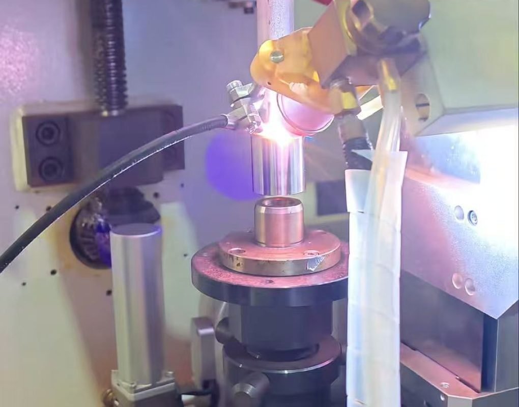
This provides an important welding advantage.
The relationship between gravity and the molten weld pool remains much more consistent throughout the complete circumference.
As a result, it becomes easier to maintain consistent:
- Weld pool behavior
- Weld bead width
- Tungsten position
- Torch angle
- Filler-wire position
- Welding speed
This is particularly useful when automatic filler wire is required.
Stable wire placement is one of the most important variables in automatic TIG welding.
For complex hydraulic tube assembly welding, a vertical rotary torch system therefore combines two important advantages:
The workpiece does not need to rotate, and the welding position remains relatively consistent throughout the complete circumference.
7. Rotary Torch Welding Is Especially Suitable for Tube Fittings
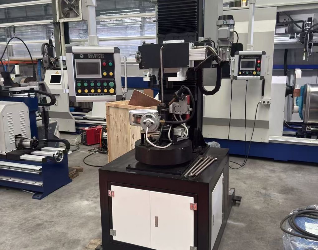
Hydraulic tube assemblies often require fittings to be welded onto both ends of a bent tube.
These fittings may include:
- Hydraulic connectors
- Threaded fittings
- Flanges
- Sleeves
- Couplings
- Special machined fittings
Using a conventional orbital head for these joints can be difficult because the head requires clearance around the weld.
With a vertical rotary torch system, the fitting and bent tube can instead be positioned in a dedicated fixture.
The machine centers the joint, and the TIG torch rotates around the weld.
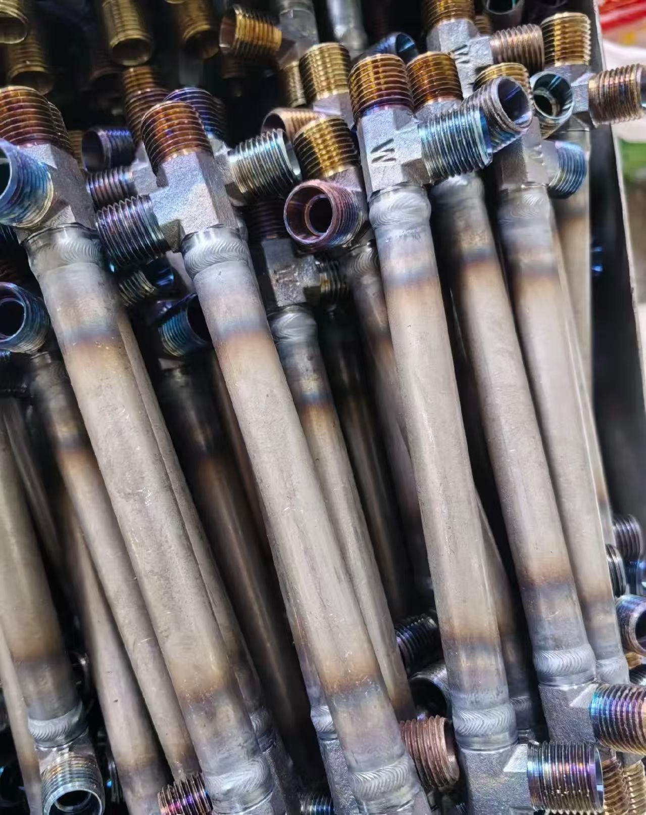
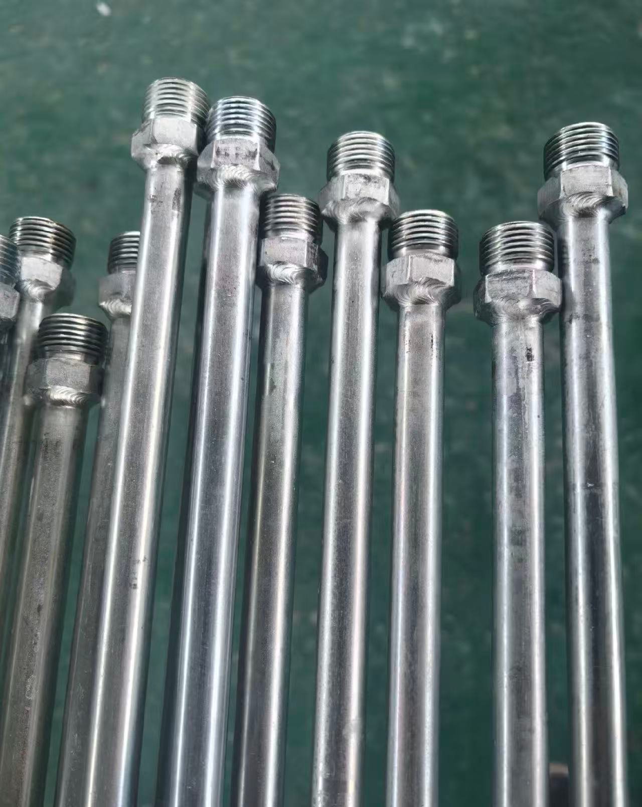
Automatic filler wire can be synchronized with torch rotation to complete the circumferential weld.
By changing the fixture, one welding machine can also accommodate different:
- Tube diameters
- Fitting designs
- Tube geometries
- Weld joint configurations
This provides greater flexibility for manufacturers producing multiple hydraulic tube assembly variants.
8. Tube-to-Tube Butt Welding Near a Fitting
Rotary torch welding is not limited to fillet welds.
The same principle can also be used for tube-to-tube butt welding, especially when the butt weld is located on a complex assembly where conventional orbital welding equipment cannot be installed easily.
The workpiece remains fixed while the TIG torch rotates around the butt joint.
Depending on the wall thickness and welding procedure, the machine can use:
- Autogenous TIG welding
- Cold-wire TIG welding
- Pulsed TIG welding with filler wire
Therefore, a rotary torch system can provide a flexible solution for both fitting welds and selected tube-to-tube butt welds on complicated assemblies.
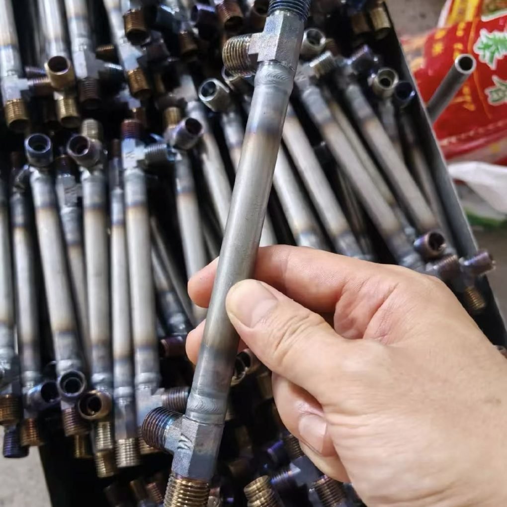
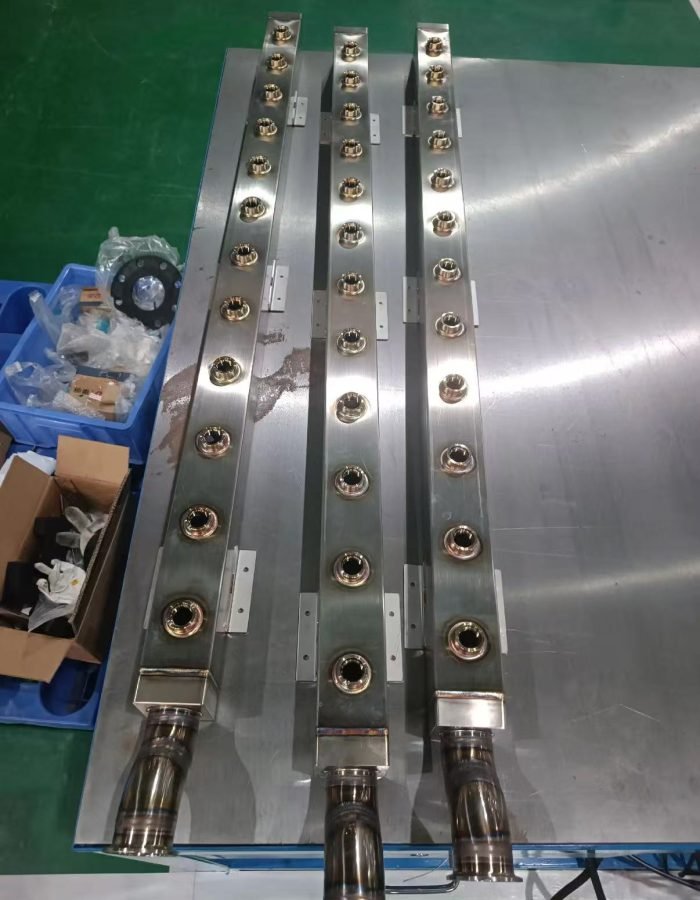
9. Branch Tubes and Saddle Welds Require a Dedicated Welding Machine
Some tube assemblies contain branch connections instead of simple circular joints.
Typical examples include:
- Main tube to branch tube
- Tee connections
- Branch pipe connections
- Tube intersections
- Nozzle connections
In these applications, the weld seam is no longer a simple circular path.
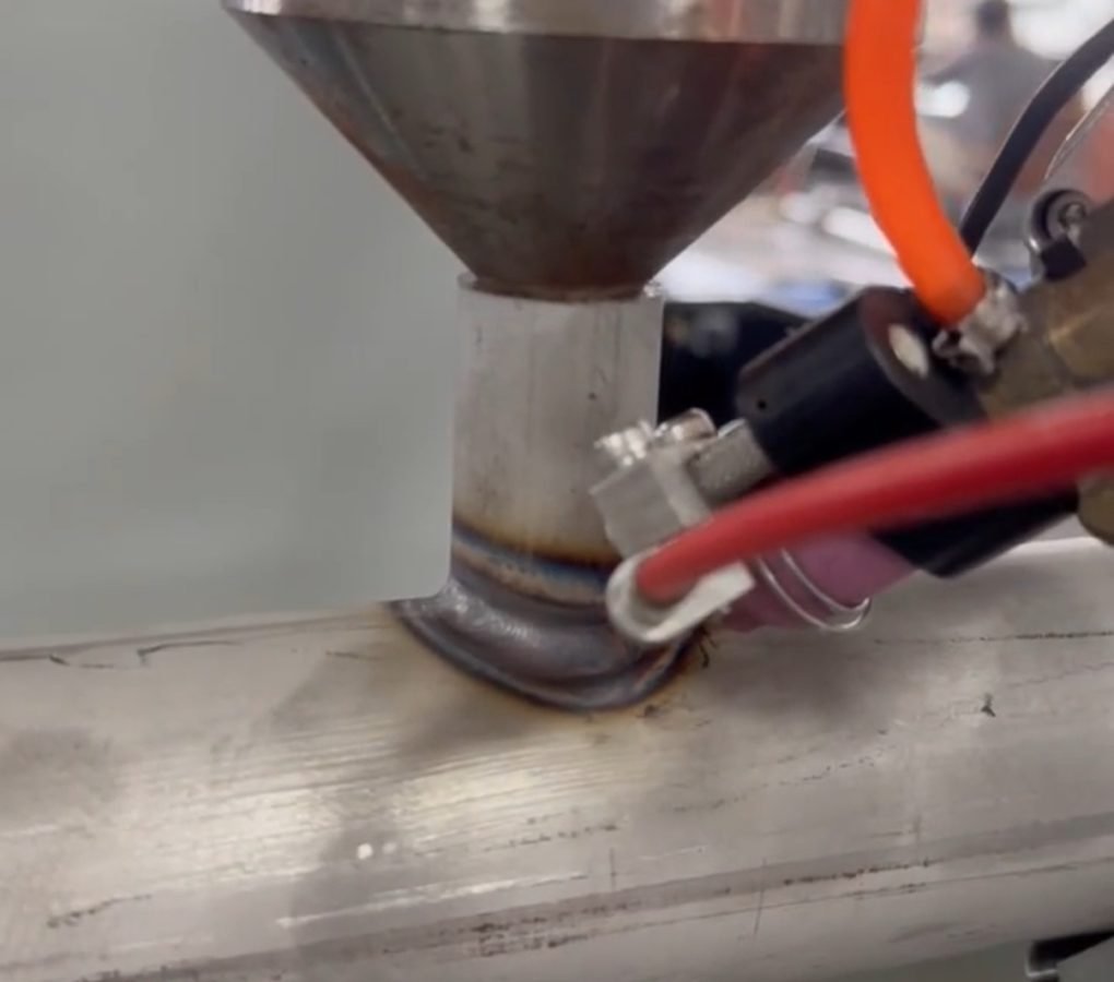
The intersection between the main tube and branch tube forms a three-dimensional saddle-shaped weld seam.
This is commonly referred to as a:
Saddle Weld or Intersecting-Line Weld
A normal rotary torch machine that only follows a circular path cannot accurately follow this geometry.
For repetitive branch welding, a dedicated automatic saddle welding machine is therefore recommended.
10. Automatic Calculation of the Saddle Welding Trajectory
One of the major advantages of a CNC saddle welding system is automatic trajectory calculation.
For a standard branch connection, the operator can input basic workpiece dimensions such as:
Main Pipe Diameter + Branch Pipe Diameter
The control system then calculates the theoretical intersection curve between the two tubes.
For more complicated joints, additional parameters can also be included, such as:
- Branch angle
- Eccentric offset
- Intersection position
- Other geometric data
The machine automatically generates the corresponding welding trajectory.
During welding, several motion axes can work together.
For example:
- A rotary axis moves the torch around the branch
- A vertical axis follows the changing saddle height
- A radial axis can compensate the torch position
- Torch oscillation can be added when required
Instead of simply following a circular path, the tungsten electrode follows the actual three-dimensional intersection between the two tubes.
This allows the machine to produce a smooth, uniform and continuous saddle weld.
Automatic saddle-welding systems available in the market also use multi-axis servo coordination and automatically generate the saddle trajectory from pipe geometry. This makes this machine architecture particularly suitable for branch-to-main-pipe welding.
11. How to Choose the Right Hydraulic Tube Welding Machine
The correct welding system should be selected according to the geometry of the tube assembly and the type of weld joint.
Straight and Short Tubes
Recommended solution:
Rotating workpiece + stationary welding torch
Typical welds:
Butt welds, fillet welds, tube-to-fitting and tube-to-flange welds
Main advantage:
Simple structure and highly stable welding conditions
Thin-Wall Bent Tubes
Recommended solution:
Closed orbital TIG welding machine
Typical process:
Autogenous TIG welding
Main advantage:
The workpiece remains stationary while the tungsten electrode rotates around the tube
Thick-Wall Tube-to-Tube Butt Welds
Recommended solution:
Open orbital TIG welding machine with filler wire
Optional functions:
Automatic wire feeding, AVC, oscillation and multi-pass welding
Main advantage:
Suitable for thicker tube-to-tube joints requiring filler metal
Complex Bent Tube Fittings
Recommended solution:
Vertical rotary torch TIG welding machine
Typical welds:
Tube-to-fitting, tube-to-flange, fillet welds and selected butt welds
Main advantage:
Ideal for complex bent tube assemblies that cannot rotate and where orbital welding head clearance is limited
Branch Pipes and Saddle Welds
Recommended solution:
Automatic saddle welding machine
Typical welds:
Main tube-to-branch tube and intersecting pipe joints
Main advantage:
Automatic calculation and tracking of the three-dimensional saddle welding trajectory
12. The Key to Automatic Tube Welding Is Choosing the Correct Motion
There is no single automatic tube welding machine that is ideal for every hydraulic tube or bent tube assembly.
The first question should always be:
Which part should rotate — the tube or the welding torch?
For short and straight tubes, rotating the workpiece while keeping the torch stationary normally provides the most stable welding condition.
For thin-wall bent tubes, orbital TIG welding allows the tube to remain stationary while the electrode rotates around the joint.
For thicker tube-to-tube butt welds, an open orbital welding head with automatic filler wire provides greater process capability.
For fittings on complicated bent tube assemblies, a vertical rotary torch TIG welding system provides much greater accessibility and flexibility.
For branch connections and saddle-shaped welds, a dedicated multi-axis saddle welding machine can automatically calculate and follow the intersecting-line trajectory.
The basic principle is simple:
Make the welding motion adapt to the tube geometry, rather than forcing every tube assembly to fit the same welding machine.
With the correct welding configuration, automatic TIG welding can be applied to a much wider range of hydraulic tubes, high-pressure tube assemblies and complex bent tube components while maintaining consistent and repeatable weld quality.
FAQ – Automatic Welding of Hydraulic and Bent Tubes
What is the best automatic welding method for a straight hydraulic tube?
If the tube can rotate freely, a rotating-workpiece automatic TIG welding machine with a stationary torch normally provides the simplest and most stable solution.
Can bent tubes be welded with orbital TIG welding?
Yes. The tube remains stationary while the orbital welding head rotates around the joint. However, sufficient clearance is required around the weld for installation and rotation of the welding head.
What welding machine should be used for thick-wall hydraulic tubes?
For tube-to-tube butt welds requiring filler metal, an open orbital TIG welding machine with automatic wire feeding is normally more suitable. AVC, torch oscillation and multi-pass welding can also be added according to the welding procedure.
How can fittings be automatically welded onto complex bent tubes?
A vertical rotary torch TIG welding machine is often the preferred solution. The tube assembly remains stationary while the TIG torch and filler wire rotate around the fitting.
Can a rotary torch welding machine perform tube-to-tube butt welding?
Yes. In addition to tube-to-fitting and fillet welding, a properly configured rotary torch machine can also perform selected tube-to-tube butt welds.
How can a saddle weld be automatically welded?
A dedicated saddle welding machine uses the main pipe and branch pipe dimensions to calculate the intersecting-line trajectory. Multiple servo axes then coordinate the torch motion so that the electrode follows the actual saddle-shaped weld seam.